Overspeed Protection System
Rotary machines are the main part of many industries. These machines are designed to work at a certain rated speed depending on the type of application. keeping machine speed, within rated limit is one of the most important roll of machine protection, if the speed exceeds the limits, serious damaged would be happened to the shaft and other parts of machine.
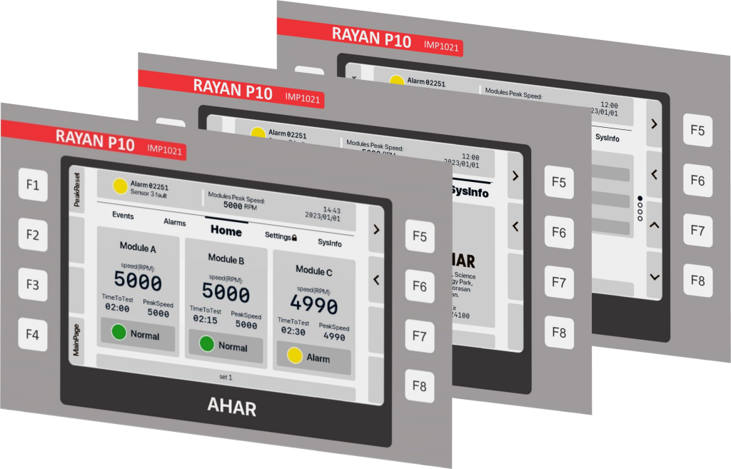
The overspeed protection system is responsible for speed detection of machine and comparing it with the user set value, then react and stop the machine in overspeed conditions.
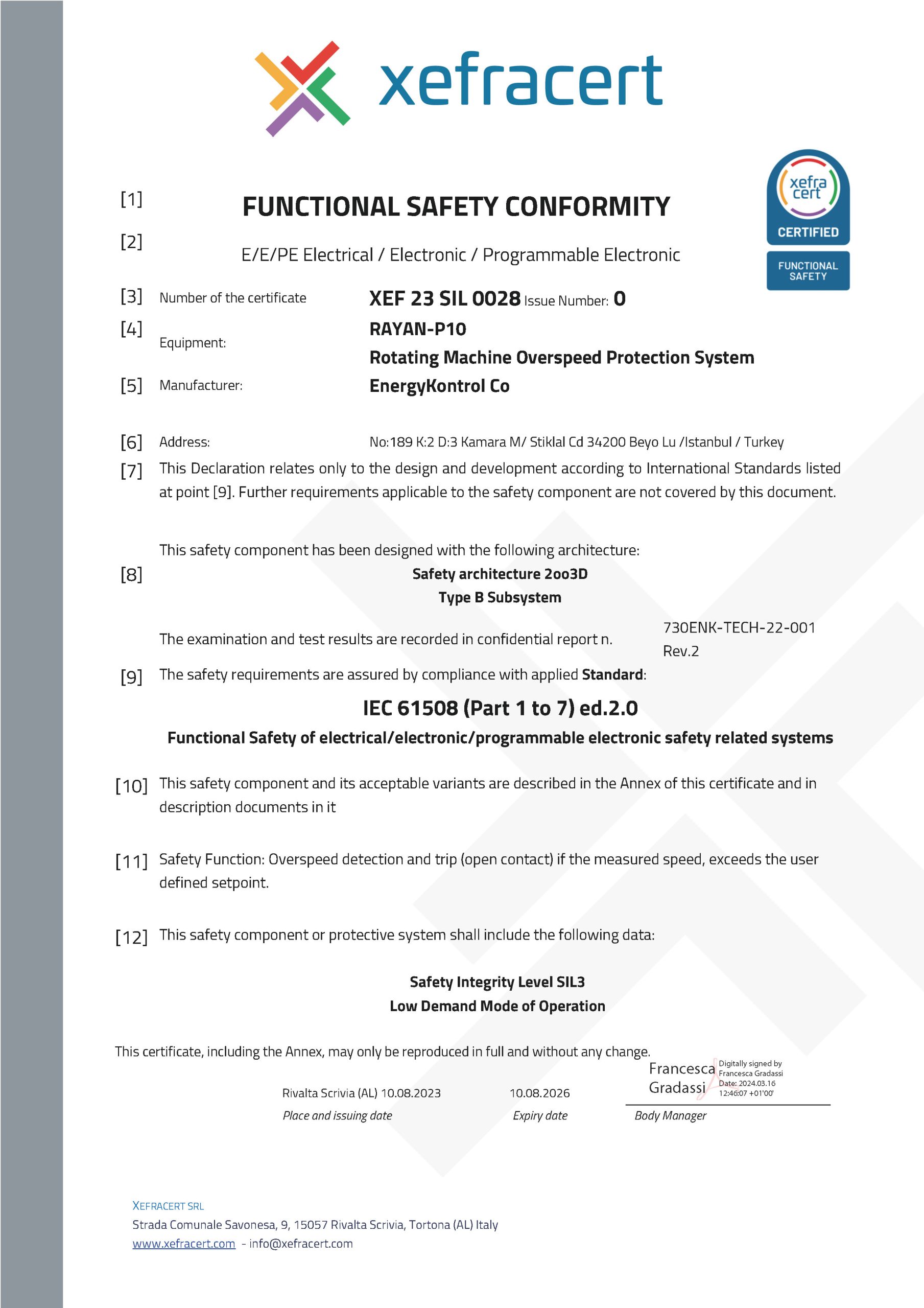
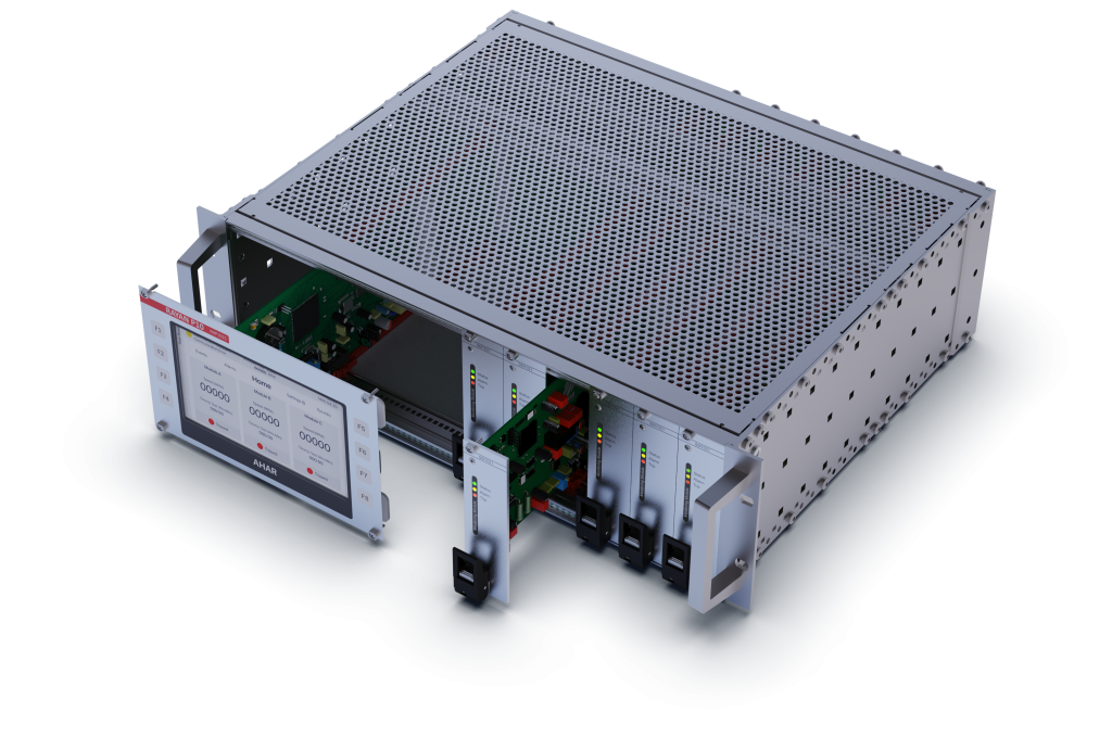
The Rayan P-10 is an overspeed protection system designed based on API670 with high level of functional safety (SIL3) in accordance with IEC 61508.
High reliability and unique features of this system make it a suitable selection for protecting all types of high level rotating machines such as turbines and generators in the critical industries such as refineries, power plants, and petrochemicals.