
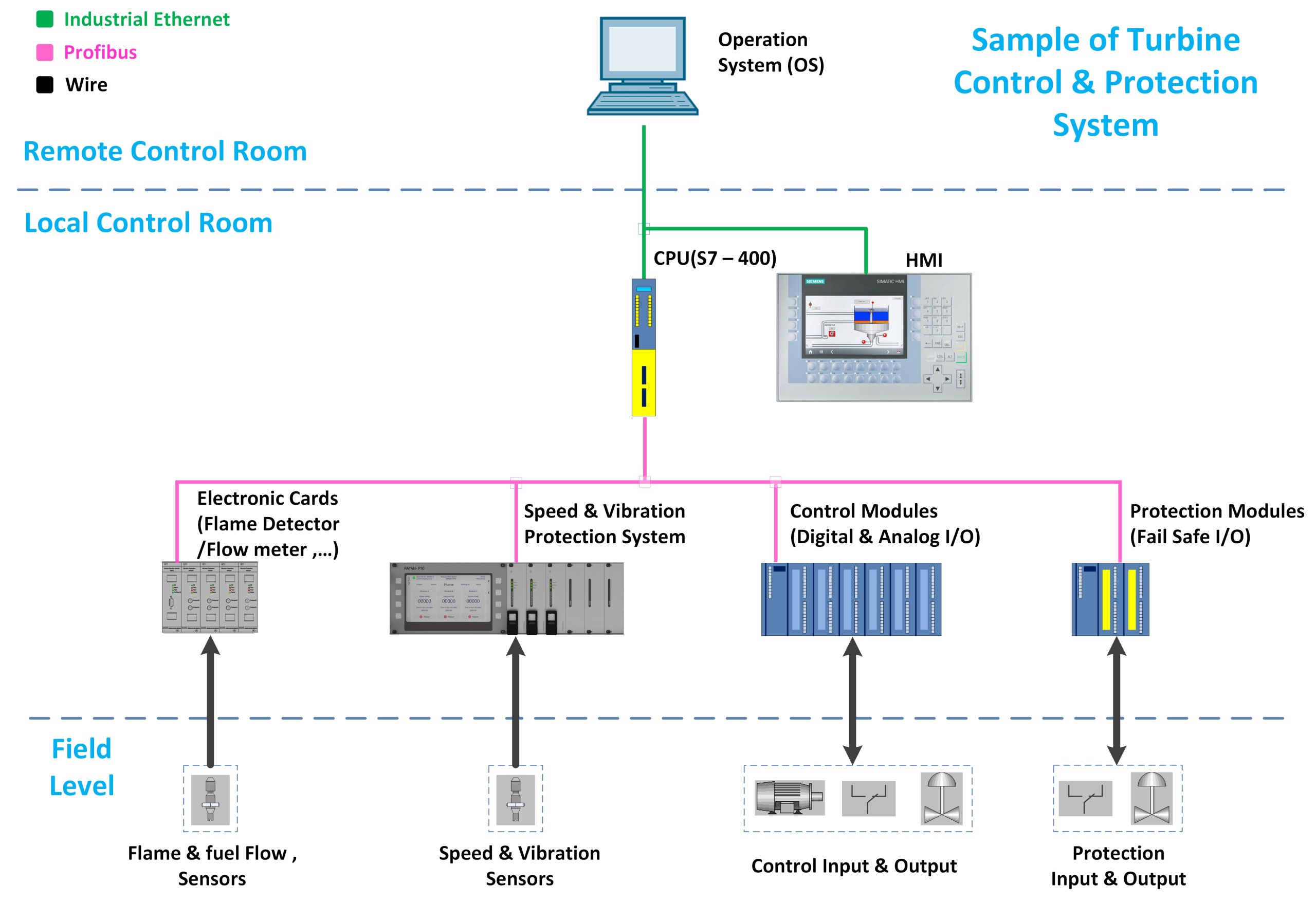
CPU
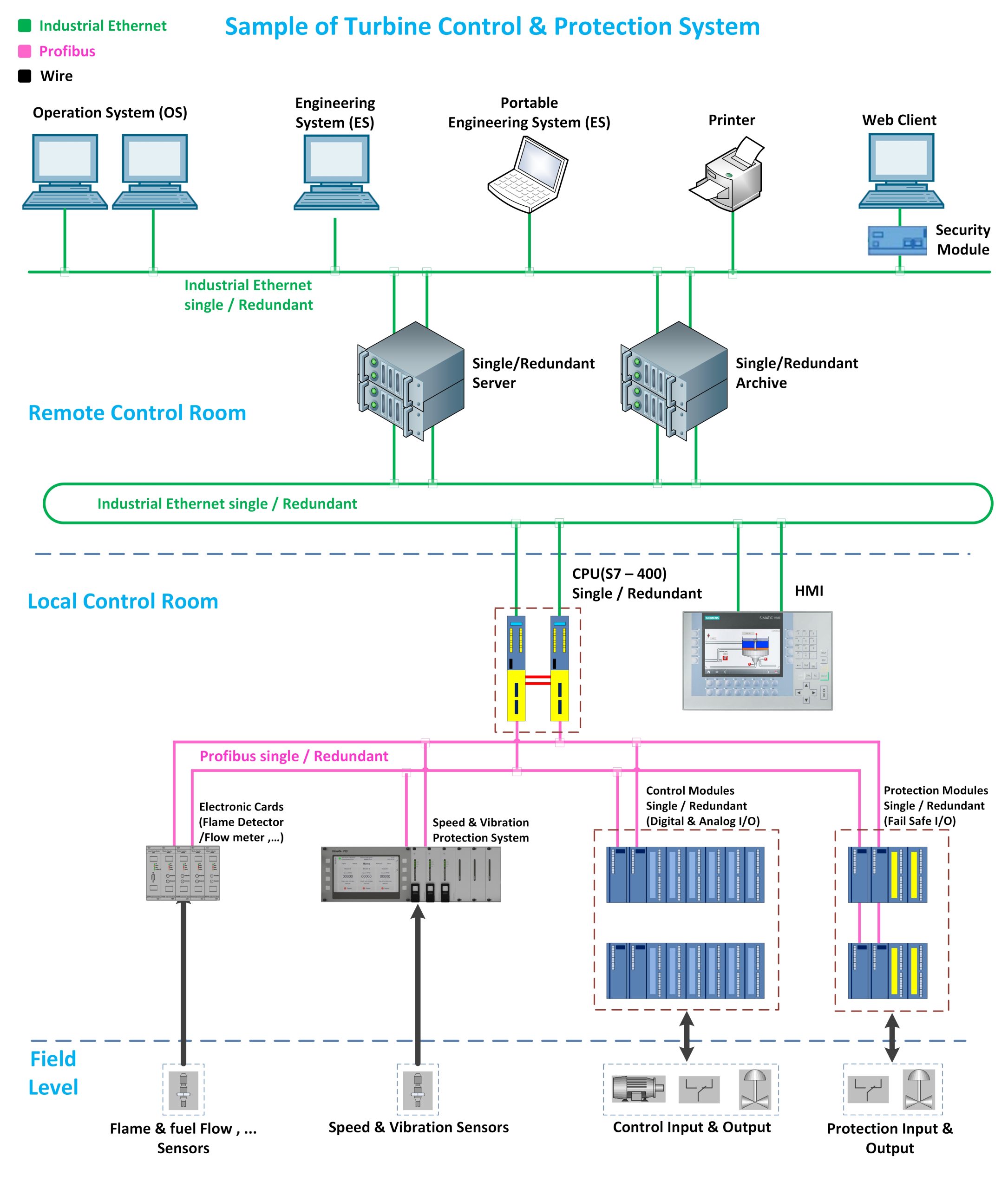
In this structure, the S7-400 processor is used, and the coding of control and protection processes is done in it. As can be seen, this processor is connected to high-level equipment such as monitoring systems via Industrial Ethernet and is connected to input and output modules via Profibus.
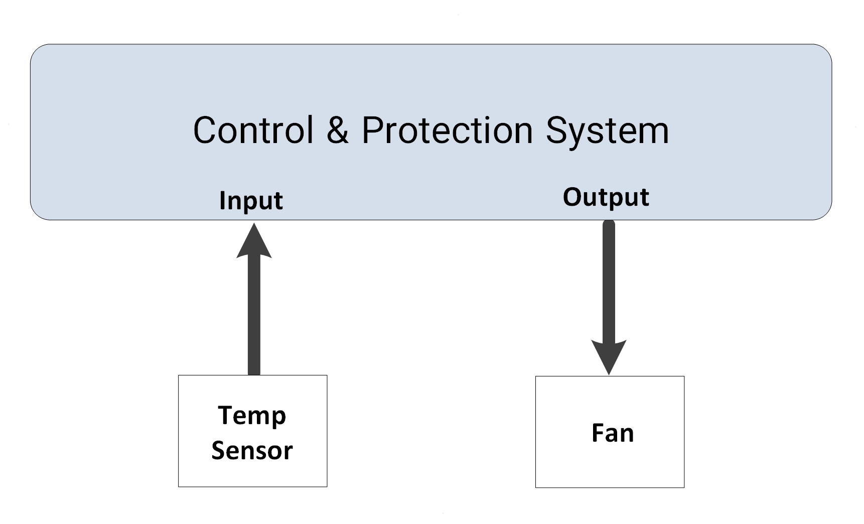
Control Modules
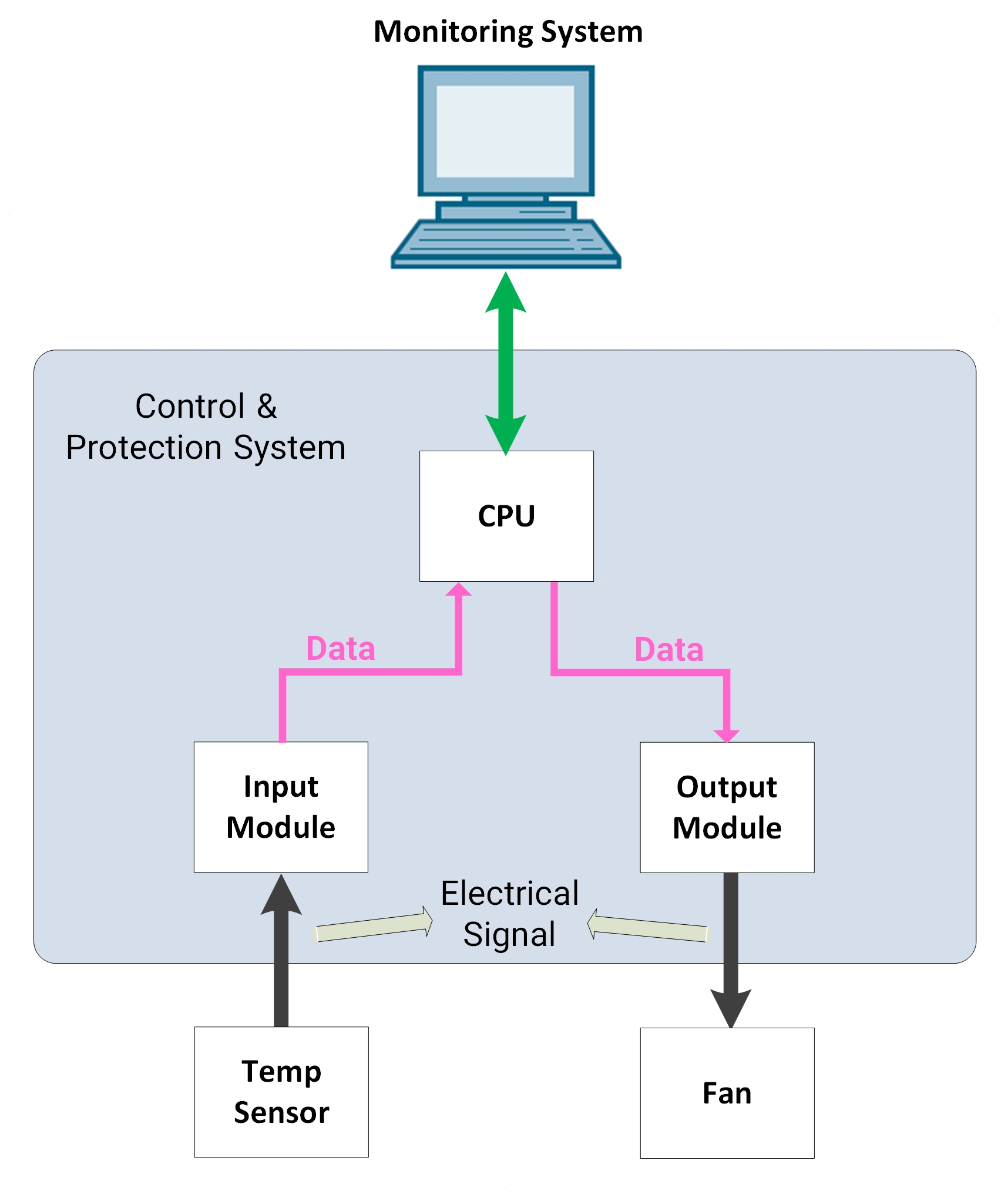
Modules of this section are used for control sections such as controlling pumps, fans, fuel valves, etc. The figure below shows this section in more detail, which will be explained in more detail below.
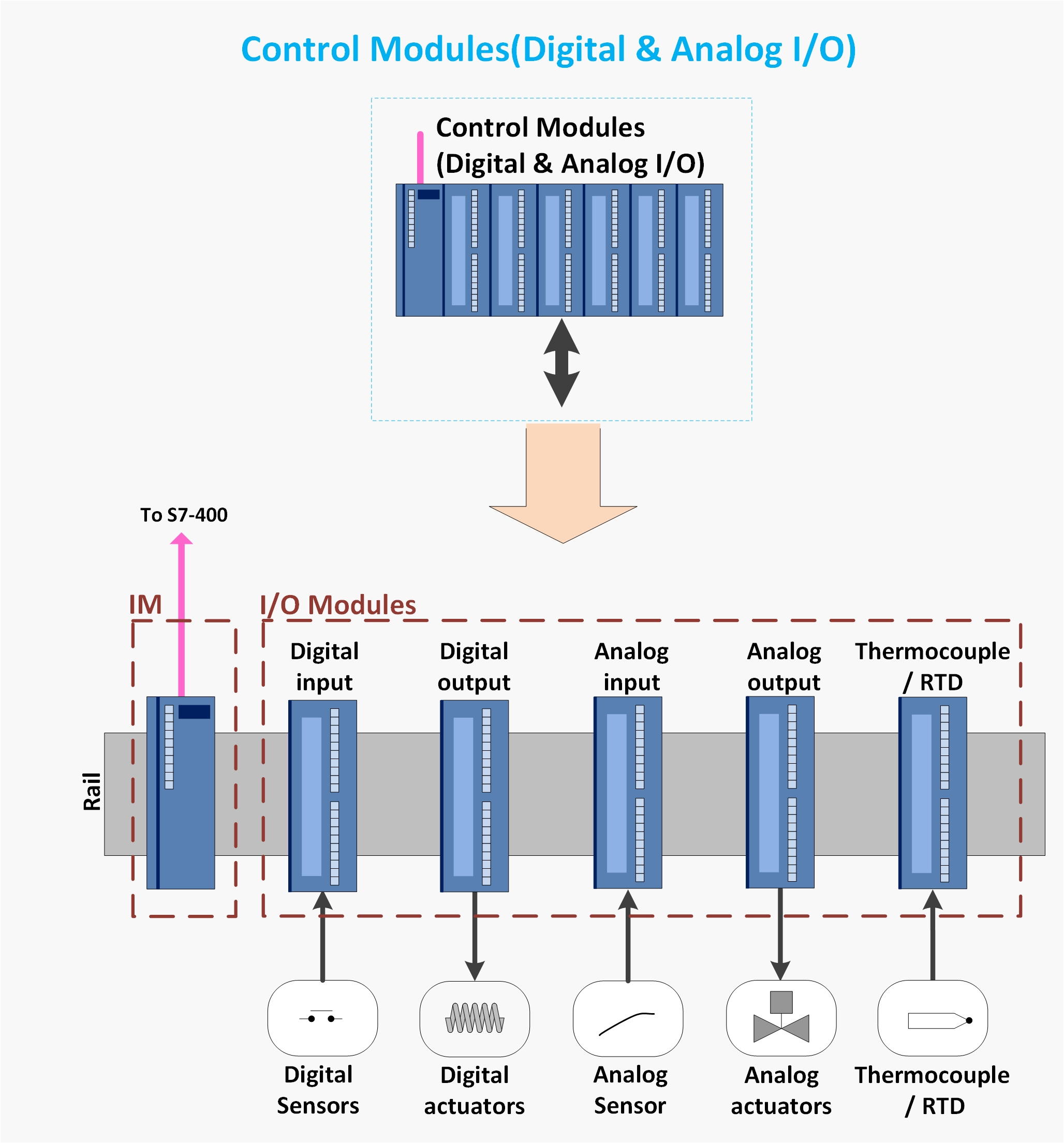
IM (Interface Module) modules are used to communicate between the processor and the input and output ports (Modules).
To communicate between the field equipment and the processor, logic and analog input and output modules are used. The modules are connected to the processor via Profibus and via the IM module. We have explained the tasks of these modules in more detail below:
– Digital Input Module
It is used to read logic statuses such as various pressure, level, push button transmitters, etc.
– Digital Output Module
It is used to command various equipment that have an On/Off state, such as various pumps, fans, etc.
– Analog Input Module
It is used to read analog signals such as oil pressure, compressor pressure, fuel valve opening position, etc.
– Analog Output Module
It is used to command fuel valves.
– Thermocouple/RTD Module
This module reads various temperature sensors and can be used to read, for example, exhaust temperature, oil temperature, etc.
Protection Modules
In the implemented structure, due to the importance of the protection section, special protection modules are used to read the turbine protection signals and command the turbine to stop.
The input and output modules selected for the protection signals are of the fail-safe type to provide more security for the protection information processing process. It is worth noting that fail-safe modules are modules that replace invalid data values with safe values. Some of the features of these modules are listed below:
– They have an independent processor from the protection processor.
– They have the ability to detect internal module problems and select a safe state.
– They can detect improper communication with the processor and select a safe state.
The figure below shows the protection section equipment in more detail, which will be explained in more detail below.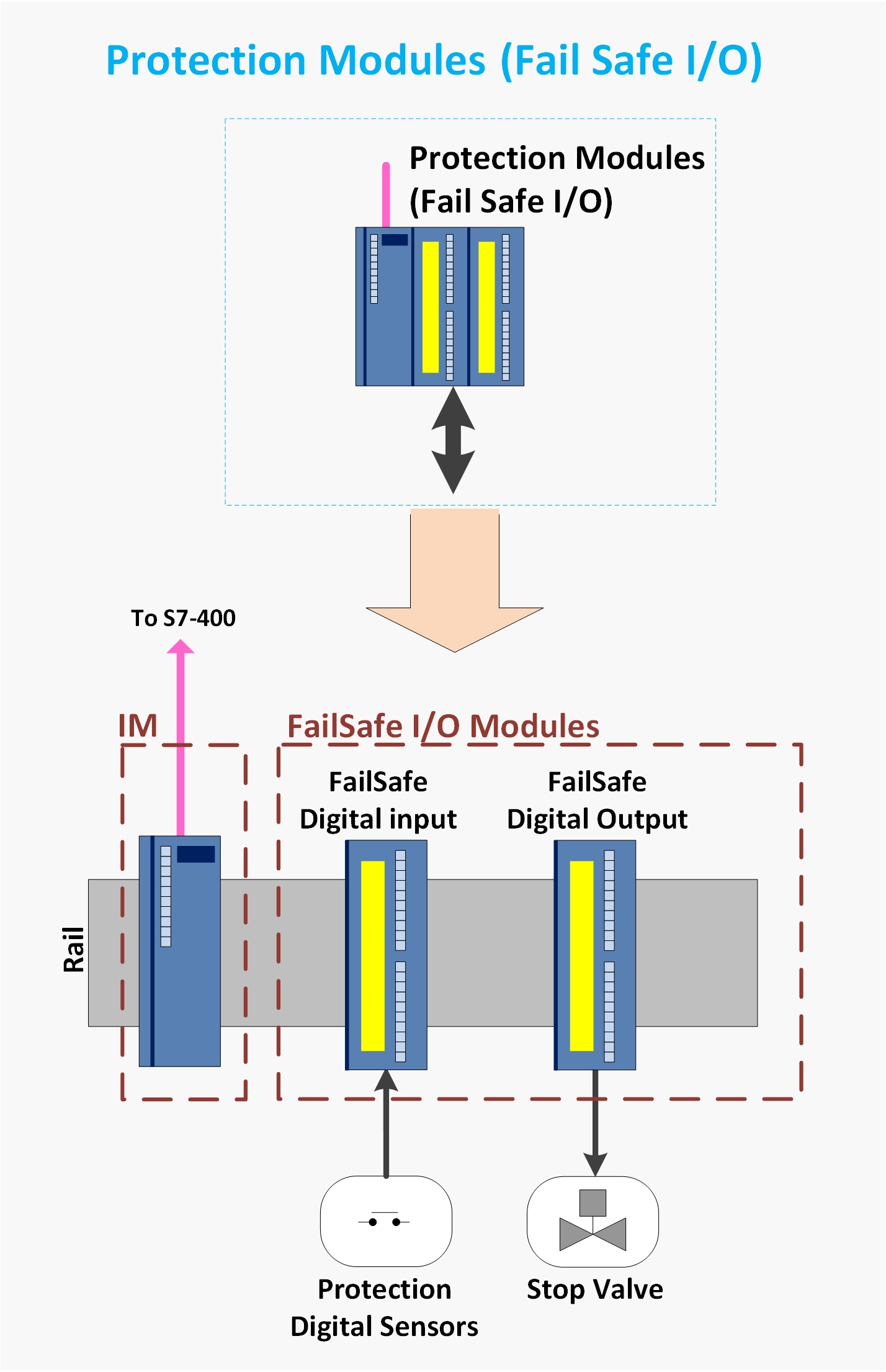
IM (Interface Module) modules are used to communicate between the processor and the input and output ports (Modules).
Logic input and output modules are used to communicate between the field equipment and the processor. The modules are connected to the processor via Profibus and via the IM module. We have explained the tasks of these modules in more detail below:
FailSafe Digital Input Module
It is used to read logic statuses such as various pressure, level, and push button transmitters, etc., which play a role in turbine protection.
FailSafe Digital Output Module
It is used to command the fuel Stop Valve. In fact, in normal turbine operation, this module issues the open command to the Stop Valve, and in dangerous conditions, it issues the close command to the valve to quickly stop the turbine.
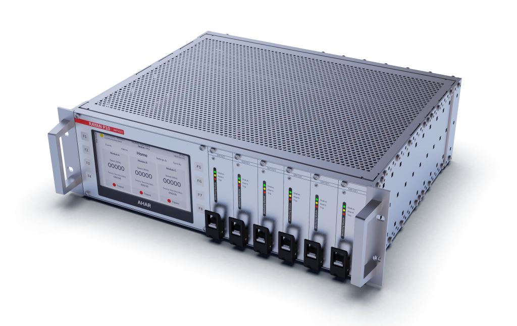
Speed & Vibration Protection System
Over-speed and vibration protection are of particular importance in turbines, so a dedicated system is provided for this purpose in the turbine protection system.
This system sends information about speed and vibration, such as instantaneous speed and vibration, alarms, and the health status of the system itself, to the processor. The processor also stops the turbine to protect it if the speed and vibration exceed the permissible limit.
However, due to the high importance of protection against over-speed and vibration of the turbine, this system can stop the unit directly and without the main processor. In fact, this system can directly command the Stop Valve to close.
This system is one of Ahar Company’s products, and its specifications can be found here.
The figure below shows the Ahar speed and vibration protection system called “Rayan“.
Explanation of the details of flame detector cards, flowmeters, etc.
To convert some signals, it is necessary to install an interface card between the sensor and the processor to convert the electrical signals of the sensors to the standard signal required by the processor. For this purpose, special electronic cards are used. Some of these cards are introduced below.
• Flame Detector Cards
It is used for the presence or absence of flame in the combustion chambers. The flame detector sensor is connected to this card and the standard signal indicating the flame status is connected to the processor.
• Flowmeter Card
It is used to measure the fuel flow. In units that operate with liquid fuel such as diesel, it is necessary to know the fuel flow to control the turbine.
• LVDT Valve Feedback Cards
In some units, LVDT is used to measure the opening value of valves such as the gas fuel valve. Since the LVDT signals must be converted to standard signals for the processor, this interface card is used.
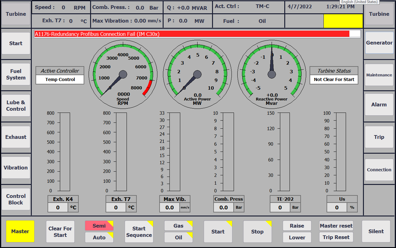
HMI Monitoring System
In the presented configuration, one HMI (Human Machine Interface) is considered on the turbine panel for monitoring and applying the required commands for operation.
This HMI has dedicated operating pages including displaying the status of the main turbine parameters such as exhaust temperature, turbine speed, vibrations, fuel path, lubrication, dedicated pages for displaying the status of the generator and excitation, displaying alarms, etc.
This equipment is selected from the highest range of Siemens multi-panels, and more information about it can be found here.
The figure below shows a sample of an HMI page implemented by this company.
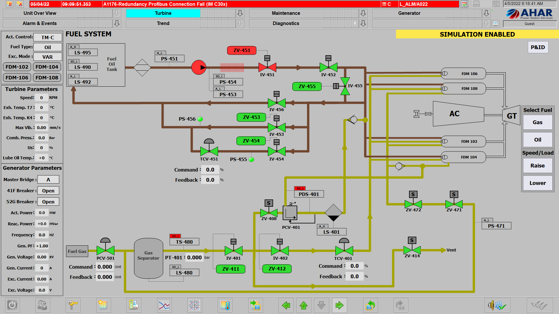
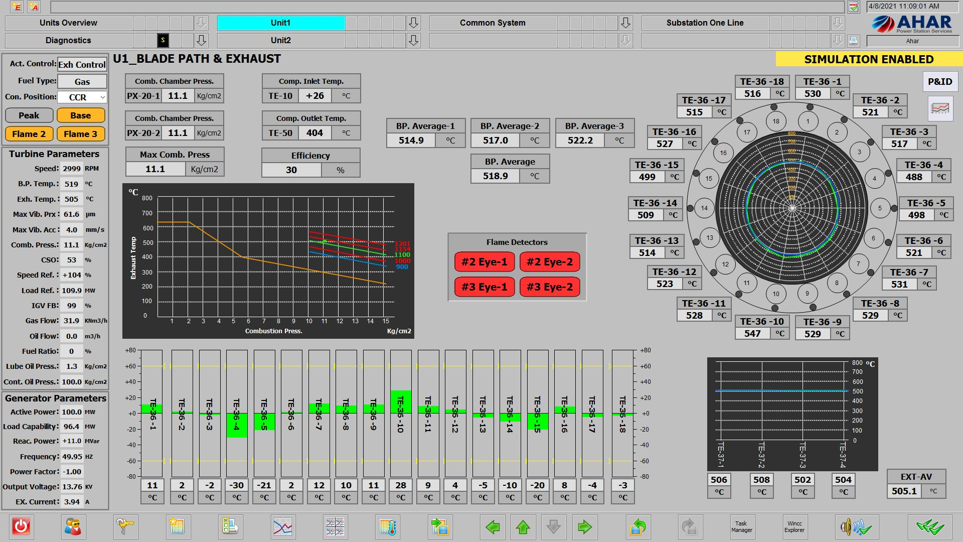
Monitoring System (Operation System)
Usually in power plants, there are rooms called the central control room which are far from the turbine and the operators in those rooms monitor the units and different parts of their complex. Therefore, in the presented configuration, an Operation System (OS) monitoring system has been considered which can be installed in a location further away from the control and protection system and the turbine parameters can be observed and commands can also be issued to it.
This system is connected to the turbine control and protection panel via an industrial Ethernet network.
This system has dedicated operating pages including unit start-up and stop, turbine status display such as exhaust temperature, compressor status, vibrations, fuel path, lubrication, combustion chambers, dedicated pages for displaying generator status, active alarms, alarm archive, etc.
In the OS system, it is possible to view and archive signal trends and all unit events are archived with high accuracy and for an unlimited time. It also has the ability to simulate and apply analog and logic values to the control system.
In these systems, the access levels of management, maintenance, operation, etc. are adjustable and each person can have access to their own information. The hardware structure of these systems is considered industrial in order to have the most stable possible state.
This computer uses Siemens’ very powerful monitoring and information processing software (WINCC).
Here are some examples of OS monitoring screens designed by this company: