Generator Excitation System

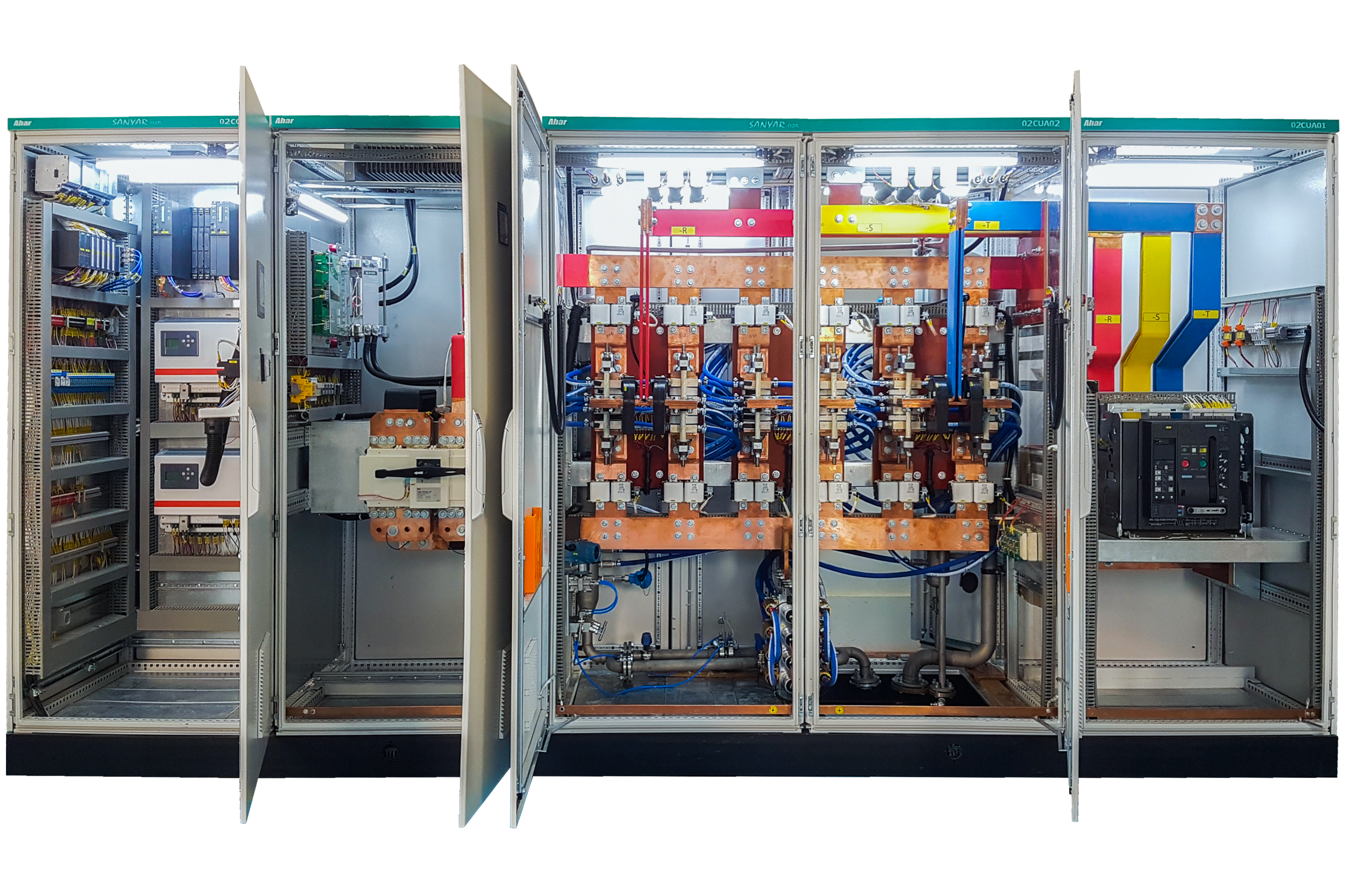
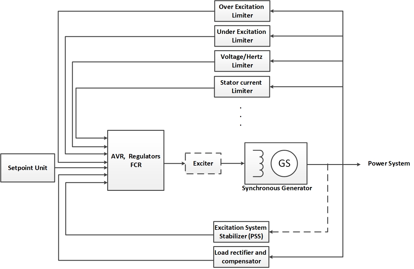
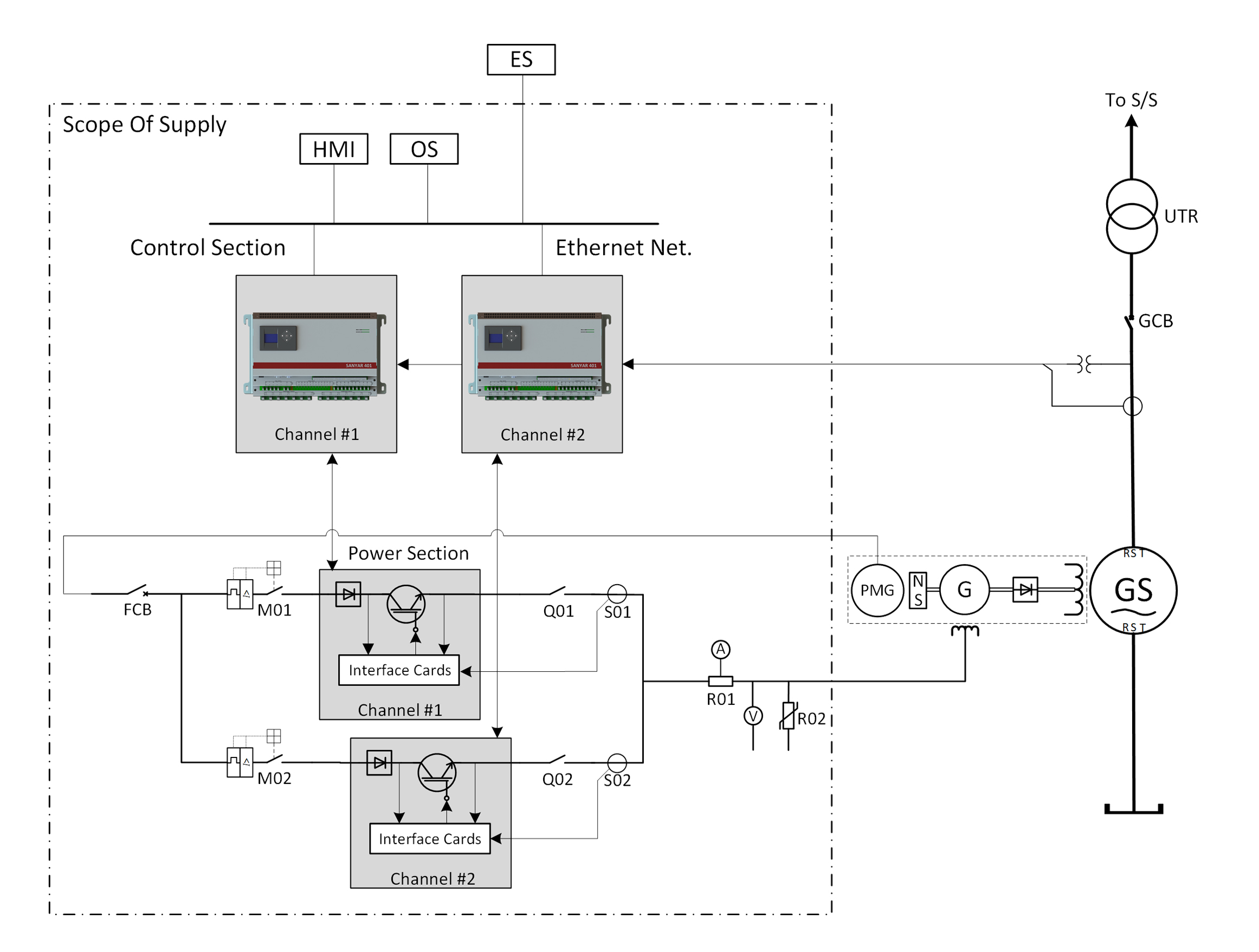
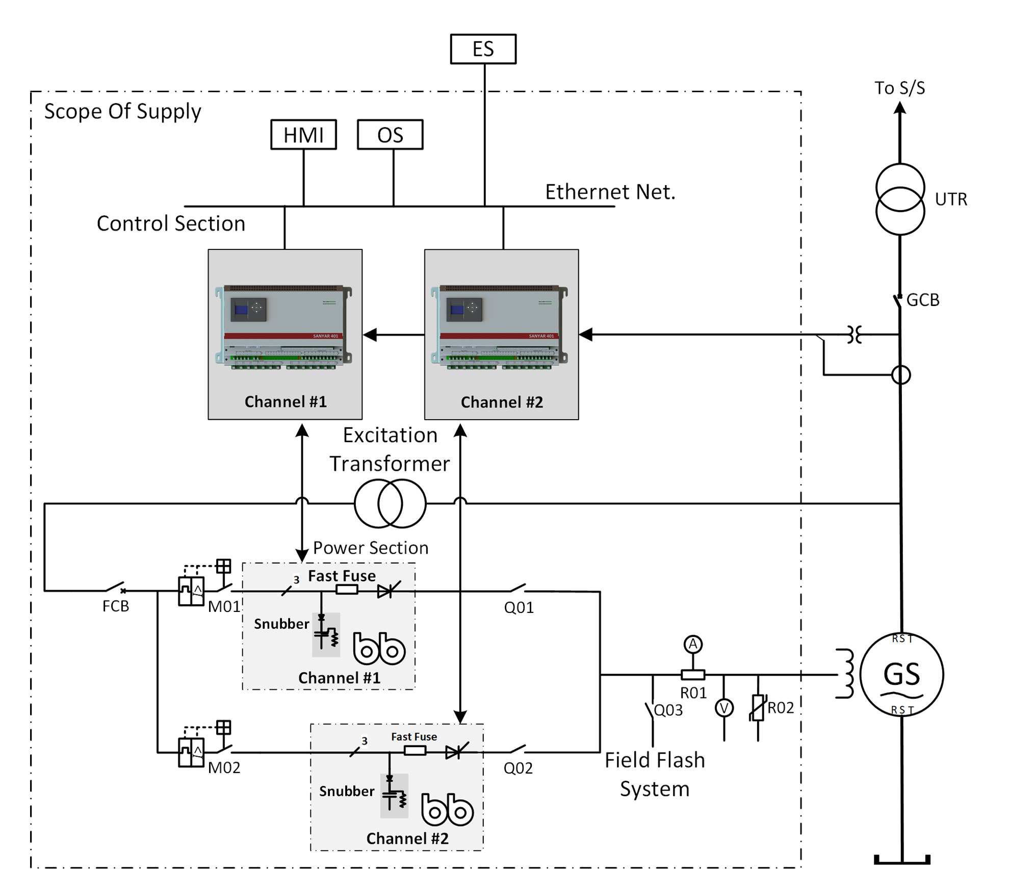
The generator excitation system is an essential component within an electrical generator, playing a critical role in ensuring the efficient and reliable generation of electricity. Its primary function revolves around supplying the requisite field current to the generator’s rotor winding. This current is responsible for establishing a magnetic field, which serves as the fundamental principle behind the conversion of mechanical energy into electrical energy. The presence of this magnetic field is paramount for the generator’s ability to produce a continuous and dependable flow of electricity.

Generator Excitation System

A generator excitation system is a vital component of an electrical generator that ensures the generation of electricity. Its primary function is to provide the necessary field current to the rotor winding of the generator, creating a magnetic field that facilitates the conversion of mechanical energy into electrical energy. This magnetic field is crucial for the generator to produce a steady and reliable flow of electricity. A well-designed excitation system contributes to the generator’s stability, transient response, and overall performance, ensuring a consistent and efficient power supply.

What is Generator Excitation System

A power plant’s operation hinges on the generator excitation system, an indispensable component that collaborates with the generator to guarantee electrical energy production. The generator itself fulfills the critical function of converting the rotational energy harnessed from a coupled turbine into a usable form of electrical energy. To facilitate this conversion and generate voltage at the generator’s output, a direct current, known as the excitation current, must be supplied. The Automatic Voltage Regulator (AVR) serves as a crucial element within the excitation system. It meticulously controls this excitation current, effectively regulating the generator’s output voltage. By precisely adjusting this current, the AVR ensures a stable and consistent voltage output, a vital aspect for reliable power delivery.
In this regard, Ahar company has produced a generator excitation system named as Sanyar.

Generator Excitation AVR System

The Automatic Voltage Regulator (AVR) is a main component of a generator excitation system that controls the generator’s output voltage by regulating the field current. It uses feedback control to continuously monitor the generator’s output voltage and adjust the excitation system accordingly.

AVR system operation described as follow:

Voltage Sensing

The AVR system includes voltage sensing circuits that measure the generator’s output voltage. This is typically done through potential transformers (PTs) or voltage transformers (VTs) that step down the generator’s voltage to a level suitable for measurement.

Voltage Regulation

The AVR compares the measured output voltage to a predetermined reference voltage. The reference voltage represents the desired output voltage level. The difference between the measured voltage and the reference voltage is the voltage error.

Error Amplification

The voltage error is amplified by the AVR using an error amplifier. The error amplifier increases the magnitude of the voltage error to generate a control signal that is proportional to the error.

Excitation Control

The control signal from the error amplifier is used to adjust the field current of the generator. The AVR modulates the excitation system, either by controlling the firing angle of thyristors in a static rectifier or by adjusting the field current of the exciter in a rotating excitation system.

Feedback Loop

The AVR system operates in a closed-loop feedback control configuration. As the field current is adjusted based on the control signal, the generator’s output voltage changes. The voltage sensing circuits continuously monitor the new output voltage, and the process repeats. This feedback loop ensures that the generator’s output voltage remains close to the reference voltage, providing voltage stability.


The AVR system is designed to provide stable and fast response characteristics. It incorporates control algorithms and parameters that determine the system’s response time, gain, and stability margins. These parameters are carefully adjusted to achieve optimal performance, ensuring that the generator can quickly adapt to load changes and maintain a stable output voltage. In order to achieve this goal, many control and protection modes have been considered. In the following the component of excitation system is shown:


Generator Excitation Control Modes

Manual Control Mode (FCR)

In the manual control mode, the operator manually adjusts the reference voltage provided to the AVR system. The operator monitors the generator’s output voltage and manually sets the reference voltage to achieve the desired voltage level. This control mode provides direct and immediate control over the generator’s voltage but requires continuous operator intervention to maintain voltage regulation.

Automatic Control Mode (AVR)

The automatic control mode is the most common mode used in AVR systems. In this mode, the AVR continuously monitors the generator’s output voltage using voltage sensing circuits. It compares the measured voltage with the reference voltage and automatically adjusts the excitation system to minimize the voltage error. The reference voltage is typically set by the system operator or based on predefined parameters. The automatic control mode provides continuous voltage regulation without the need for constant operator intervention.

Reactive Droop Compensator and Line Droop

In a reactive droop compensator, the controlled voltage is transferred into the generator and is usually used for generators that are parallel to each other (the ability to absorb the reactive power of the generator). In line droop compensation, the controlled voltage is transferred to the outside of the generator (the ability to generate reactive power for the generator). This type of droop is mostly used in systems where the network is powered by a generator for a long time. The amount of droop can be changed from ES/OS system. The amount of droop can be adjusted as a percentage of the generator voltage and between 0 and 30%.

VAr / Cosφ Control Mode

VAr reactive power control mode and cosφ power factor control mode are used when the generator is parallel to the power grid. In reactive power control mode, the reactive power excitation system controls the generator output or consumption to a value set by the user. In power factor control mode, the reactive power excitation system changes the generator so that the unit power factor is set to the set value.

Voltage Ramp Rate Control Mode

In certain applications where rapid load changes occur, the AVR system may incorporate voltage ramp rate control. This mode limits the rate at which the generator’s voltage can change over a specific time period. By controlling the rate of voltage change, the AVR system prevents rapid voltage fluctuations that could affect connected equipment or disrupt the stability of the power system.

PSS Controller

PSS stands for Power System Stabilizer, which is an essential component of a generator excitation system. A Power System Stabilizer is a control device that is designed to improve the dynamic stability of a power system, particularly during disturbances or variations in the system’s operating conditions. It works in conjunction with the excitation system of the generator to provide additional damping to oscillations and maintain system stability.

Generator Protection Functions

The Automatic Voltage Regulator (AVR) system in generator excitation systems incorporates several protective functions to ensure the safe and reliable operation of the generator.

Here are some common protective functions provided by AVR systems:

AVR systems monitor the generator’s output voltage, and if it exceeds a predetermined threshold, the AVR activates protective measures. It may reduce the field current or limit the excitation system to prevent the voltage from rising to unsafe levels. Overvoltage protection safeguards the generator and connected equipment from voltage-related damage.

AVR systems also include under-voltage protection to detect and respond to a significant decrease in the generator’s output voltage. If the voltage falls below a specified threshold, the AVR takes corrective actions to increase the field current or excitation level to restore the voltage to a safe and operational range. Under-voltage protection prevents sustained low voltage conditions that can lead to equipment malfunction or instability.

AVR systems include field failure protection to detect the loss of field current in the generator’s excitation system. If the field current is interrupted or lost, the AVR initiates protective actions to prevent voltage collapse and the subsequent loss of synchronization. Field failure protection typically involves activating a fast-acting voltage control mode or disconnecting the generator from the grid to avoid damage and ensure system stability.

Reverse power protection is a function of the AVR system that protects the generator from operating as a motor. If the generator is unintentionally driven by the grid instead of supplying power, the AVR detects the reverse power flow and activates protective measures. These measures may include reducing the excitation level or disconnecting the generator from the grid to prevent damage and ensure correct operation.

AVR systems may include protective functions to monitor the frequency of the generator’s output voltage. If the frequency exceeds or falls below predefined thresholds, the AVR takes appropriate actions to regulate the excitation system and maintain the frequency within acceptable limits. Overfrequency and underfrequency protection helps maintain system stability and protect connected equipment.

Although not directly related to the AVR system, some generator excitation systems may integrate overcurrent protection. This protection monitors the generator’s output current and activates protective measures if the current exceeds safe operating limits. Overcurrent protection prevents the generator and associated equipment from damage due to excessive current flow.

In addition to preventing the stator end area from overheating, this limiter does not allow the generator operating point to reach outside the allowable stability range. If the generator is not operating within the allowable stability range, it will become unstable with the error. This function also limits the amount of reactive power that the generator absorbs from the network. The generator under excitation curve can be implemented by 10 points in the software.

This limiter always monitors the current of the generator field to prevent that from overloading. This function has a cooling section to prevent damage to the rotor during repetitive current forces. This limiter is active in all control modes.

This limiter monitors the stator current and prevents it from overloading. In general, it can be said that this function is mostly used in units where the turbine power is much higher than the generator power. If the stator current is more than the regulated pickup current, after the specified time, the excitation current is changed so that the generator operating point enters the safe zone.

After measuring the voltage and frequency, this limiter calculates the ratio of volts per hertz so that if it is out of the normal range, after a time delay (depending on the ratio of volts per hertz), it controls the excitation current and lead the generator voltage to the allowed range.


In the following figure, the limitation of generator which is design in sanyar is shown.

Types of Generator Excitation System

There are several types of generator excitation systems used in power generation applications. The choice of excitation system depends on factors such as the generator’s size, application, and desired control capabilities. The classification of the excitation system is shown in the following figure.

Here are some common types of generator excitation systems:

DC Excitation System

In a DC excitation system, a separate DC generator or rectifier supplies the field current to the generator’s field winding. The DC source allows for precise control and regulation of the generator’s output voltage.

AC Excitation System

In an AC excitation system, an auxiliary alternator or an exciter connected to the generator’s shaft supplies the excitation current. The AC exciter output is rectified to DC using diodes or thyristors before being supplied to the generator’s field winding. AC excitation systems offer simplicity and reliability.

Brushless Excitation Systems

Brushless excitation systems eliminate the need for brushes and slip rings, providing a more reliable and maintenance-free solution. These systems use rotating diodes or rotating rectifiers mounted on the generator shaft to convert the AC output of an auxiliary alternator to DC for excitation. Brushless excitation systems are widely used in large generators and offer enhanced control and reliability.

Static Excitation Systems

Static excitation systems replace the rotating components of traditional excitation systems with solid-state devices. These systems use power electronic devices, such as thyristors or insulated gate bipolar transistors (IGBTs), to control the excitation current. Static excitation systems provide fast response and precise control over generator voltage and are commonly used in modern power plants.

Generator Redundant Excitation System

Redundancy in Engineering is one of the most important considerations for critical and sensitive applications such as power systems, avionics, and medical equipment. In power plants, redundancy in control systems, especially in generator excitation systems, guarantees the reliability and safety of operation. In a generator, redundant excitation system more than one excitation system drives the generator, and if under any circumstance fails, the redundant exciter can drive the generator. It should be noted that a generator redundant excitation system must be guaranteed fail-safe operation, which means that the reserve or redundant system should excite the generator with the lowest transition time and without any trip or emergency shutdown. Any fault trip or emergency shutdown in a power plant or similar utilities causes considerable property damage to the power plant, consumers, and distribution network. So designing and implementing a generator redundant excitation system is a high-tech and complex task that only some companies worldwide can do.

Generator redundant excitation system solution

Generally, a generator excitation system contains a low-power or control section and high power or power bridge system that thyristors or IGBTs arrays are placed in this section. In a redundant generator excitation system solution, redundancy should be considered in both the control and power sections. Sanyar 401 is the heart of the SANYAR generator excitation system and can be applied in a redundancy mode. Also, from the power section point of view, the power bridge has two main configurations, including 1+1 and n+m configurations.

The 1+1 configuration falls into two 50/50 and 100/0 redundancy types. In the 50/50 configuration, two power bridges are utilized, each passing 50% of the excitation current. In 100/0 redundant generator excitation, all excitation currents pass through a power bridge (100%), and other power bridges are set in a reserve state. In the n+m configuration, there are n operational power bridges and m reserve or redundant power bridges. For example, in a 4+2 configuration for 2000A excitation current, each operational or main power bridge passes 500A current, and two power bridges are considered as redundancy.

Generator Excitation System Standards

  • IEEE Std 421.1: IEEE Standard Definitions For Excitation Systems for Synchronous Machines
  • IEEE Std 421.2: IEEE Guide for Identification, Testing and Evaluation of the Dynamic Performance of Excitation Control system
  • IEEE Std 421.3: IEEE Standard For High-Potential Test Requirements for Excitation Systems for Synchronous Machines
  • IEEE Std 421.4: IEEE Guide for the Preparation of Excitation System Specifications
  • IEEE Std 421.5: IEEE Recommended Practice for Excitation System Models for Power System Stability Studies
  • IEEE Std 421.6: IEEE Recommended Practice for the Specification and Design of Field Discharge Equipment for Synchronous Machines

EMC Standards

  • IEC 61000-4-2: EMC- Part 4-2: Electrostatic discharge immunity test (ESD)
  • IEC 61000-4-3: EMC- Part 4-3: Radiated, radio- frequency electromagnetic field immunity test (RFI)
  • IEC 61000-4-4: EMC- Part 4-4: Electrical fast transient/burst immunity test (Burst)
  • IEC 61000-4-5: EMC- Part 4-5: Surge immunity test (Surge)
  • IEC 61000-4-8: EMC- Part 4-8: Power frequency magnetic field immunity test

Environmental Standards

  • IEC 60068-2-1: Environmental testing- Part2-1: Tests- Test A:Cold
  • IEC 60068-2-2: Environmental testing- Part2-2: Tests- Test B:Dry heat
  • IEC 60068-2-30: Environmental testing- Part2-30: Tests- Test Db: Damp heat

If you want more information, enter your email