Synchronous Motor Drive
In order to generate electrical power through a generator, a device is needed that will drive the generator at its rated speed and thereby convert mechanical energy into electrical energy. This device, which is called a motor or turbine, has different types that are classified according to the type of power plant and generator. In general, there are three types of turbines: water, steam, and gas, which are used to start generators. Of course, there are other turbines that are less used in the world for electricity generation, such as wind turbines.
In hydroelectric power plants, the primary force for driving the turbine and generator assembly is the pressure of water accumulated behind dams. Due to the structure of these power plants, the water force of the dams has the ability to start the turbine and generator assembly from an initial speed of zero while the system is at rest. The control system of the water inlet valves determines the amount of water entering the turbine blades, and the turbine can start moving from the moment of rest.
In steam generators, this is done with steam power, and in fact the starting system in these power plants is steam power. However, in gas power plants, a separate drive is required to rotate the assembly, apart from the above. This is where the topic of starting gas turbines comes up.
In a gas turbine, compressed air plays a crucial role in two key aspects:
1. Fuel Combustion: Compressed air acts as the oxidizer for the fuel being burned in the combustor. Similar to how we need oxygen to start a fire, compressed air provides the necessary oxygen molecules for efficient fuel combustion in the gas turbine. Without sufficient compressed air, the fuel wouldn’t burn completely, leading to wasted fuel and reduced power output.
2. Energy Transfer: The compressed air itself carries significant potential energy due to the work done by the compressor to squeeze it. This hot, high-pressure air then enters the turbine section. As it expands through the turbine blades, it loses pressure and converts that lost pressure into kinetic energy. This kinetic energy is then used to spin the turbine shaft, which in turn drives the generator to produce electricity.
In order to produce compressed air, an initial startup system is required. There are different ways to start the system, which will be discussed further.
Using an initial launcher
In this method, the turbine is rotated by a starter, such as an induction motor or a diesel generator. This rotation continues until the necessary compressed air is supplied by the compressor and the turbine can turn the generator alone.
The problem with this method is that it requires an initial setup. This launcher imposes a large initial cost on the system. Also, this method has a high maintenance cost. The main advantage of this method is the simplicity of implementation.
Use of a primary starter
In this method, the turbine is rotated by a starter, such as an induction motor or a diesel generator. This rotation continues until the necessary compressed air is supplied by the compressor and the turbine can rotate the generator on its own.
Drawbacks
- High initial cost: The system requires a primary starter, which can be expensive.
- High maintenance cost: The starter requires regular maintenance, which can be costly.
Advantages
- Simplicity: This method is relatively simple to implement.
Starting a generator as a synchronous motor
Another method for starting the system is to convert the generator into a motor to rotate the system. In this method, the synchronous machine is initially operated as a motor. After the turbine has reached speed and the air has been compressed sufficiently to allow the turbine to continue operating, the synchronous machine is taken out of motor mode. At the end of the startup process, and when paralleling, the synchronous machine can be used again as a synchronous generator. There are two common methods for this, which are briefly explained below.
Starting a synchronous motor as an asynchronous motor
In this method, the synchronous motor’s rotor winding is initially short-circuited. The rotating stator field then induces a voltage in the rotor, which causes the motor to start moving like an induction motor. This is achieved using squirrel cage bars placed on the rotor. The voltage is induced in these bars, which creates a magnetic field and causes the motor to rotate.
Once the motor has started rotating asynchronously and reached its synchronous speed, the excitation system is connected and the motor continues to operate synchronously.
Drawbacks
- This method complicates the motor design, making it larger and more expensive.
- This method is not widely used in industry and is mainly used in laboratories.
Use of static frequency converter (SFC) systems
In this method, the frequency of the stator magnetic field is initially kept low so that the rotor’s DC field can lock onto the stator’s rotating field and the motor starts rotating. In this method, the motor’s supply voltage must be increased from a low amplitude and frequency to the system’s nominal amplitude and frequency by a drive system. This method is much more complex than other methods.
An important point in this method is that for the motor to rotate correctly, the position of the rotor must be known at all times so that the stator windings can be energized accordingly. Therefore, sensors must be used for this purpose. Sensorless methods are also being considered today. These methods are also complex.
Due to the various capabilities and advantages of SFC systems, they have received a lot of attention in various industries. Later in this document, we will get to know these systems better.
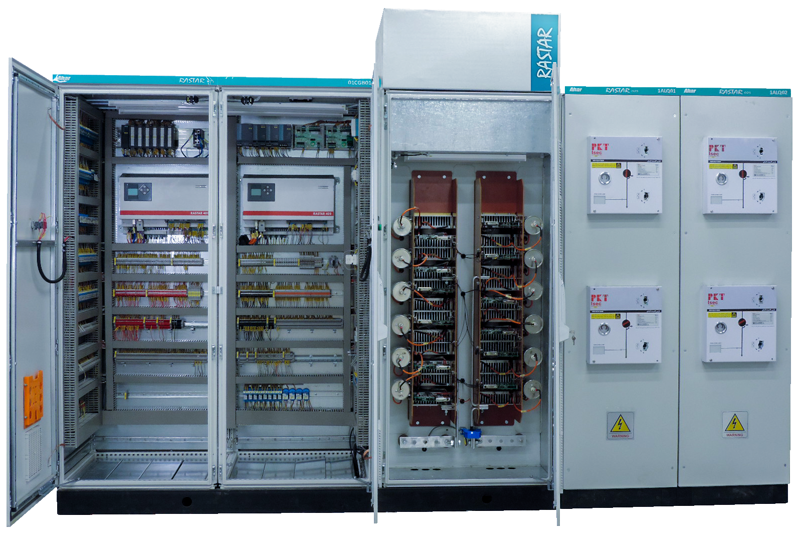
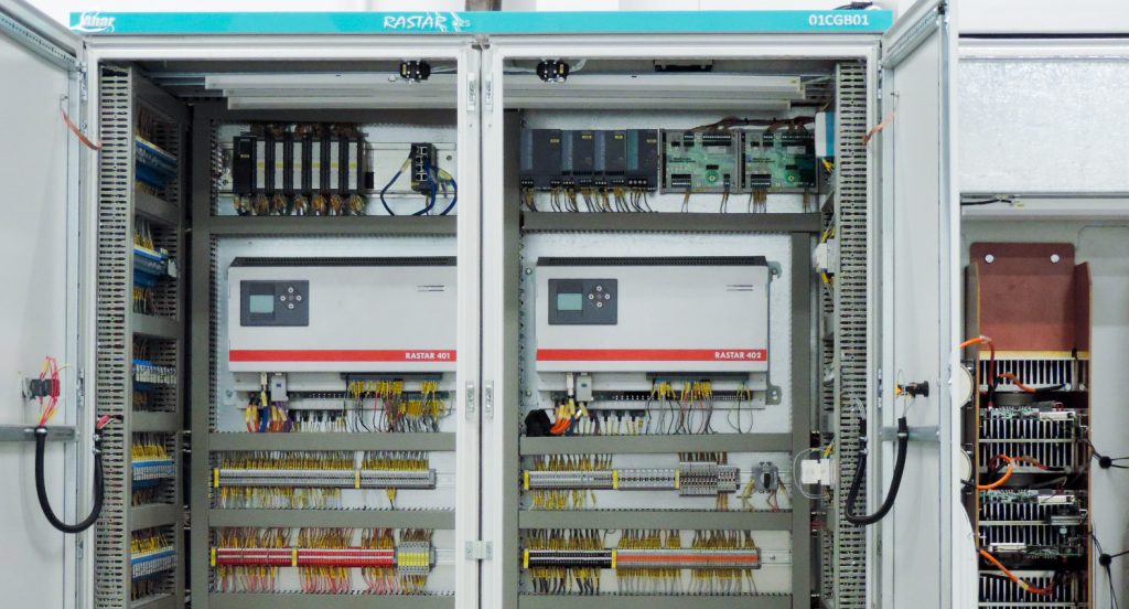
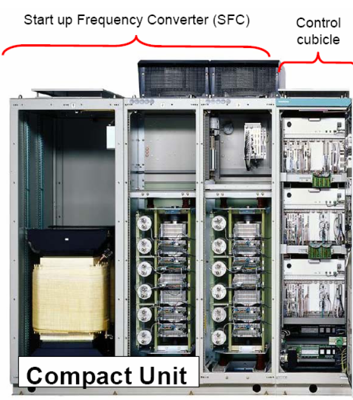
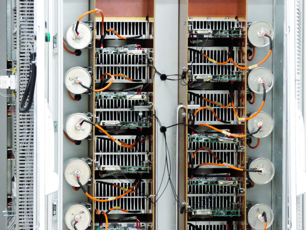
As mentioned in the previous section, starter systems have a complex structure. They are made up of electronic cards, high-speed processors, powerful microcontrollers, and power system devices such as switches, transformers, power bridges, and so on. The figure below shows an example of a starter system.
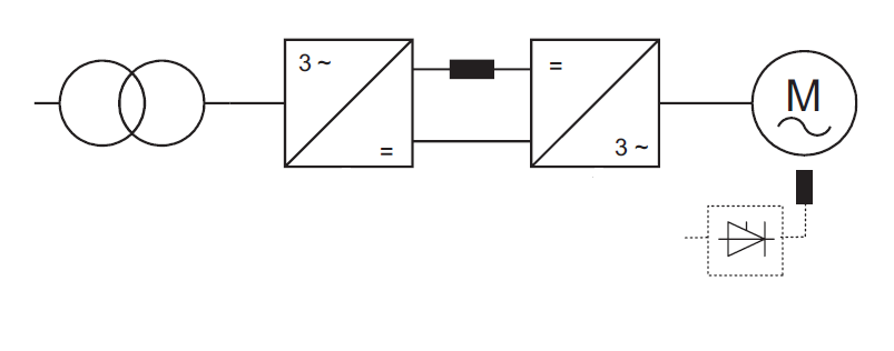
In general, the SFC power bridge section consists of a rectifier bridge and an inverter bridge.
• The rectifier bridge converts the input AC voltage to DC voltage.
• The inverter bridge converts the DC voltage to a controlled AC voltage.
• This AC voltage is used to power the synchronous motor.
• The two power bridges are connected to each other by a DC reactor.
Figure below shows the structure of the SFC power bridges.
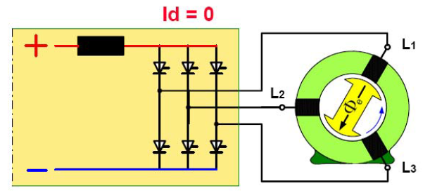
The power semiconductor switch used in starter systems, which have high current and voltage, is often a thyristor.
• Thyristors turn on when the voltage across them is positive and a firing pulse is sent to their gate.
• To turn off thyristors, the current must be removed from them.
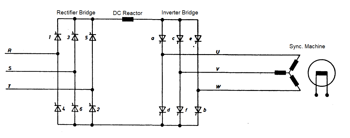
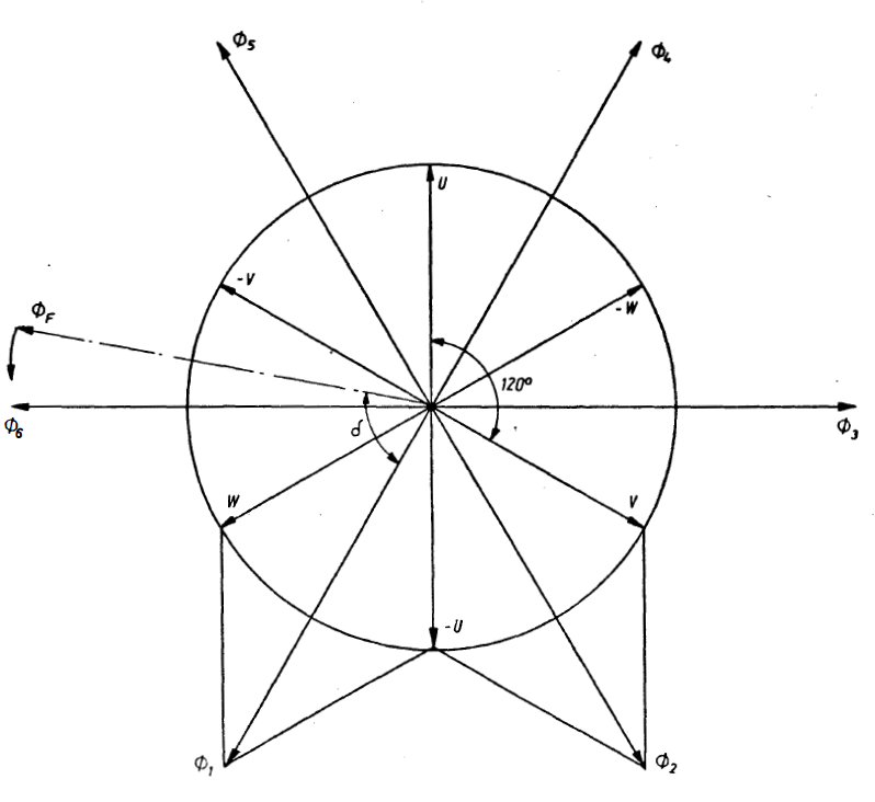
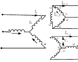
As it is clear in the above figure, turning on two thyristors a to f will cause two windings of the stator of the synchronous machine to be energized. This injected voltage causes current to flow and generate a magnetic field. This rotating magnetic field must have a suitable position compared to the fixed field of the rotor so that it can bring the rotor with it and cause the motor to rotate. The figure below shows the rotor field and the state of the stator fields when each phase is energized. According to this figure, if the rotor field is in the fΦ position, it is necessary to establish the stator field in the 1 position in order to generate the counterclockwise rotation and produce the maximum torque. For this, phase W must have a positive voltage, and phase U must have a negative voltage. This is provided by driving thyristors a and b.
As shown in the figure above, turning on two of the thyristors a to f will energize two of the synchronous machine’s stator windings.
• This injected voltage causes current to flow and a magnetic field to be generated.
• This rotating magnetic field must have the correct position relative to the rotor’s fixed field in order to entrain the rotor and cause the motor to rotate.
The figure below shows the rotor field and the stator field conditions when each phase is energized.
• According to this figure, if the rotor field is in position fΦ, in order to create counterclockwise rotation and produce maximum torque, the stator field must be established in position 1.
• For this to happen, phase W must have a positive voltage, and phase U must have a negative voltage.
• This is achieved by gating thyristors a and b.
Here are some additional details about the stator windings:
• The stator windings are typically made up of copper wire.
• The stator windings are typically located in the slots of the stator.
• The stator windings are connected in a star or delta configuration.
If the drive system activates a field other than 1Φ, the rotor movement will be affected and the motor will not rotate properly. Therefore, the control system must know the exact position of the rotor at all times.
There are various methods for reading the rotor position. Some systems use tachometers, others use resolvers, and still others use optical sensors to read the rotor position. New SFC systems use sensorless methods to read the rotor position. These methods offer greater reliability and lower maintenance costs due to the absence of sensors.
The figure below shows how the rotor moves and follows the stator field when two thyristors are turned on. As shown in the figure, the rotor starts to move counterclockwise in the direction of the resultant field Φi. When the rotor reaches the resultant field, the inverter thyristors are switched to create a new resultant field in another position, which causes the rotor to continue moving. This method creates a continuous rotor movement and the rotor field always follows the rotating stator field.
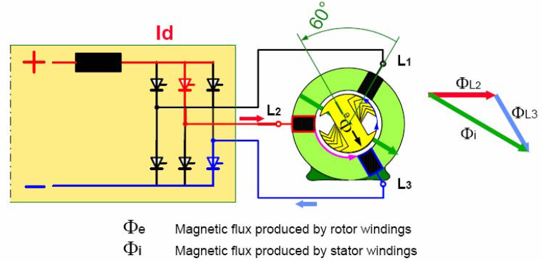
As mentioned, in order to turn on thyristors, the voltage across them must be positive and a turn-on gate pulse must be issued. To turn them off, the voltage across the thyristor must be made negative to remove the current flowing through it, and then the thyristor can be turned off.
At the beginning of the system startup, the voltage of the machine is low due to the low speed. The amplitude of this voltage is too low to turn off the thyristors. Therefore, a method called Force Commutation or Pulse Mode is used at the beginning of the startup.
In this method, at the beginning of the startup when the voltage amplitude is low, in order to turn off the inverter thyristors, the current is forcibly removed from the inverter thyristors by changing the function of the rectifier bridge to an inverter bridge. This causes them to turn off. This process usually continues up to 8% of the rated speed. Thereafter, the thyristors will turn on and off naturally in the Natural Commutation mode.
Torque control methods in synchronous motors
At the beginning of the gas turbine startup, more torque is required to overcome the inertia of the turbine and compressor. As the unit gains speed, the torque required to rotate the turbine decreases. Later in the startup, when the turbine burners are ignited, part of the torque production will be taken over by the turbine, and as a result, the synchronous motor will need to produce less torque. As mentioned, during the system startup, the torque generated by the synchronous motor needs to change several times, so the starter system must be able to control the machine’s torque well during the startup process.
According to the torque equation in synchronous machines, which is given below, the torque is proportional to the product of the machine voltage and the induced voltage in the sine of their phase angle (load angle); The parameter K in this equation is a constant.
T= k EA VΦ sin δ
As a result, there are two control parameters for torque control. The induced voltage parameter of the machine, EA , is effective in the production or consumption of reactive power by the machine and cannot independently change the torque of the machine.
• Voltage injected into the machine, VΦ
• Changing the load angle
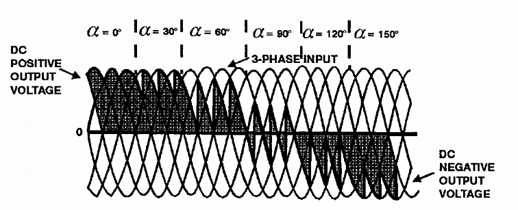
In order to change the amplitude of the injected voltage, given that the input voltage to the system is constant (this voltage is supplied by a power transformer), it is necessary to control the amplitude of the voltage using a controllable power bridge. In the starter system, this is done by the rectifier bridge. By controlling the firing angle of the thyristors of this bridge, the output voltage of the bridge and hence the amplitude of the voltage injected into the machine can be controlled. Figure below shows the voltage amplitude as a function of the firing angle. As can be seen from this figure, the output voltage of the rectifier bridge increases as the firing angle decreases.
Therefore, by controlling the firing angle of the rectifier, the voltage injected into the synchronous machine can be controlled, and hence the torque can be adjusted and controlled.
Another parameter that affects torque control is the load angle. The load angle is the angle between the induced voltage and the voltage injected into the machine. As mentioned, the rectifier bridge converts the input AC voltage to a DC voltage with a variable amplitude. The inverter bridge has the ability to convert the input DC voltage to an AC voltage with a variable frequency. The control and drive system can also read the machine voltage and turn the inverter bridge thyristors on and off in such a way that the output AC voltage of the inverter bridge is phase-shifted relative to the input voltage to the rectifier bridge. This phase shift is equivalent to the load angle. Therefore, by controlling the turning on and off of the inverter thyristors, the load angle and hence the torque can be controlled.
Therefore, the machine voltage is controlled by the rectifier bridge and the load angle is controlled by the inverter bridge in the starter system in order to control the torque.
Function of the excitation system in the starter system
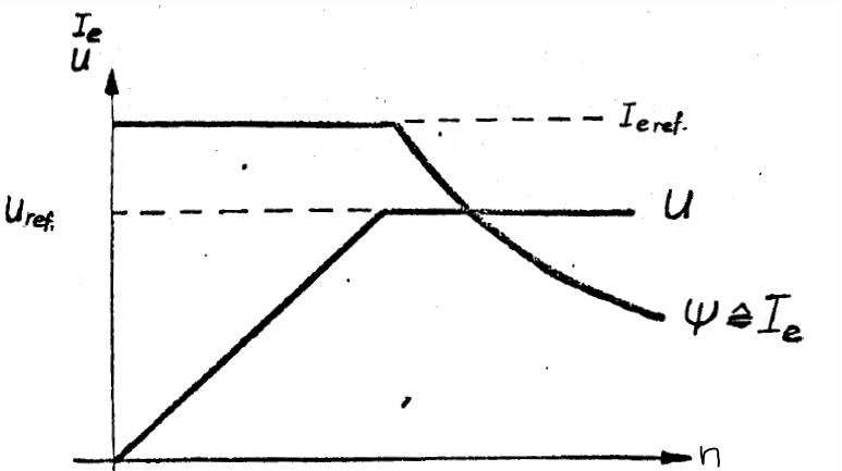
The excitation system in synchronous motors is responsible for generating the voltage EA. This voltage is proportional to the speed of the machine and the flux produced (proportional to the excitation current). At the beginning of the startup, due to the low speed of the machine, the excitation system injects the maximum regulated current into the machine rotor to generate the required voltage (this current is usually about 30% of the rated excitation current at full load). After that, with the increase of the unit speed, the induced voltage increases. As a result, in order to prevent overvoltage of the motor, it is necessary to control the induced voltage by the excitation system. This voltage control is achieved by reducing the excitation current.
The figure below shows how the excitation current is reduced when the induced voltage reaches the rated value of the machine. According to this figure, after the speed increases and the induced voltage reaches the reference value, the excitation system starts to reduce the excitation current in order to control the induced voltage.
Advantages and capabilities of the starter system
Turbine starter systems have many advantages. This is why these systems have been attracting the attention of industrialists for some time. Some of the general advantages of these systems include the following:
Ability to use one starter system to start multiple gas turbines
A starter system can start multiple gas turbines independently and asynchronously. As a result, there is no need to purchase a starter system for each turbine separately. This will lead to significant cost savings. Other methods of starting synchronous motors, such as using diesel generators or starter motors, do not have this capability.
Having various capabilities due to the use of programmable electronic cards and also programmable PLCs
State-of-the-art starter systems offer a wide range of capabilities to the user. These features facilitate operation, reduce maintenance, improve system troubleshooting, and ultimately reduce costs. One of the important capabilities of starter systems is to start the motor in different operating modes. Modern starter systems have several main starting modes, which will be described in more detail below.
Normal Mode Start
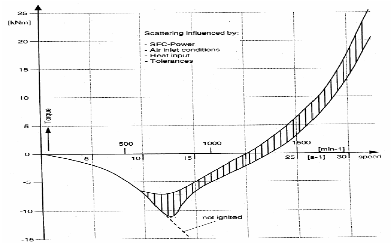
In this operating mode, the starter system rotates the turbine to a speed of about 2100 RPM (35 Hz) and then disengages. All turbine starter systems have this mode. At a frequency of about 10 Hz to 15 Hz, the turbine burners are usually lit and the turbine generates torque on its own. Also at a frequency of about 20 to 25 Hz, the turbine reaches the required torque to rotate the generator. However, due to the existence of critical speeds for the turbine, the starter system assists the turbine to start up to a frequency of 35 Hz. The following shows the torque curve of a gas turbine startup.
According to this figure, at a frequency of about 23 Hz, the turbine torque is sufficient to continue the startup, but the starter system remains in the circuit until a frequency of 35 Hz.
Washing Mode
Due to the accumulation of combustion products on the turbine blades, it is necessary to clean and remove them. The starter system can be used for this purpose. In this mode, the starter system rotates the turbine at a specific and constant speed, allowing it to be washed.
Turning Mode
In units that do not have a Turning Gear, it is possible to rotate the turbine at low speeds for a long time using this mode of the starter system. This mode usually rotates the turbine at a speed of about 100 RPM.
Black Start Mode
In very special cases when the grid experiences a blackout, this mode can be used to start the turbine and inject electricity into the grid through the generator. To use this mode, a diesel generator must be placed instead of the transformer at the input of the rectifier bridge. This capability of the starter system is very valuable in terms of the auxiliary services of power plants.
Condenser Mode
In some cases, to correct the power factor of the network, the generator is used as a capacitor or an inductor. To do this, the generator is disconnected from the turbine and the network, and then using the starter system, the generator is rotated to a frequency of 52.5 Hz, which is equivalent to 105% of the rated speed. Through the operation of the excitation system at this speed, the generator can play the role of a reactive power controller in the network. This capability of the starter system is very valuable in terms of the auxiliary services of power plants. This mode is also known as Phase Shift Mode.
Brake Mode
When using the condenser mode, the generator is not connected to a load, so the time it takes to slow down and reach zero speed is long. In these cases, the braking mode of the starter system is used to reduce the speed of the generator more quickly. This mode acts as a brake for the generator and causes it to slow down quickly. After the generator speed has been reduced by this mode and the generator has reached zero speed, the generator is reconnected to the system and the system can be restarted using the starter system.
Purging Mode
In combined cycle power plants that also include a boiler, if the startup process is not successful for any reason during the startup phase and the system stops, the combustion gases will accumulate in the boiler. These gases must be removed from the path before the next startup can begin. For this reason, in these types of power plants, the SFC system has an additional operating mode compared to normal startup. In this mode, the gas turbine burners are not lit and the turbine acts as a fan, blowing air into the boiler to remove the excess gases. To do this, the SFC system rotates the turbine at a frequency of 10 Hz, which is equivalent to 20% of the rated speed, for 8 to 12 minutes, and then automatically disengages.
Increased system reliability
Any system or capability that can prevent a power plant unit from shutting down or reduce the probability of a system outage will increase the reliability of electricity generation. Due to the aforementioned capabilities of starter systems, they have higher reliability compared to other startup methods due to less maintenance requirements, faster troubleshooting, and etc. With these systems, the probability of problems occurring during the startup and shutdown process of the unit is much lower.
In order to better explain the advantages and capabilities of the starter system, the following table compares the SFC system with the starter motor startup.

Different Implementations of the Startup System
Startup systems have different configurations depending on the type of application in gas turbines or heavy and super heavy synchronous motors, as well as the requirements of the installation site. In this section, several practical configurations of the SFC system are briefly described. It is worth noting that in cases where the voltage level of the system increases, two or more series thyristors are used instead of one thyristor in the power bridges. Also, with increasing current, two or more parallel thyristors can be used instead of one. In the configurations that will be described below, the topic of series and parallel connection of thyristors can also be implemented in the same configurations.
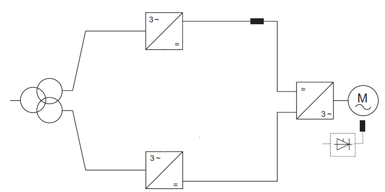
6-Pulse Configuration
This configuration is the most common type of SFC system. The figure below shows a diagram of this configuration.
The 6-pulse configuration is so named because it uses six thyristors, three on each side of the DC link. The thyristors are fired in a specific sequence to produce a three-phase AC voltage waveform.
The transformer in this configuration is a conventional two-winding power transformer. The primary winding of the transformer is connected to the AC input voltage, and the secondary winding is connected to the DC link.
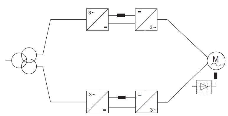
12-Pulse Configuration
The 12-pulse configuration is a more sophisticated type of SFC system that has a number of advantages over the 6-pulse configuration. The 12-pulse configuration produces a lower level of harmonics and has a higher power factor.
The 12-pulse configuration is shown in the figure below.
As can be seen from the figure, the rectifier section of this configuration consists of two 6-pulse bridges, for a total of 12 pulses. The inverter section has one 6-pulse bridge.
This configuration requires a three-winding transformer. The two output windings of the transformer are connected in a star-delta configuration.
The 12-pulse configuration operates as follows:
The thyristors in the rectifier section are fired in a specific sequence to produce a 12-pulse DC voltage waveform. The firing sequence is determined by the control system.
The 12-pulse DC voltage waveform is applied to the inverter section. The thyristors in the inverter section are fired in a specific sequence to produce a 12-pulse AC voltage waveform.
The 12-pulse AC voltage waveform has a lower level of harmonics than the 6-pulse AC voltage waveform. The 12-pulse AC voltage waveform also has a higher power factor.
The 12-pulse configuration is typically used for high-power applications, such as starting large motors.
Here are some of the advantages of the 12-pulse configuration:
- The lower level of harmonics
- Higher power factor
- Reduced motor losses
- Reduced torque pulsations
- Improved motor performance
Here are some of the disadvantages of the 12-pulse configuration:
- More complex than the 6-pulse configuration
- More expensive than the 6-pulse configuration
- Requires a three-winding transformer
12-Pulse Configuration
The 12-pulse configuration is another commonly used configuration for SFC systems. It is mostly used in heavy-duty synchronous motors. In this configuration, each of the rectifier and inverter bridges consists of 12 thyristors. The figure below shows this configuration.
In this configuration, the SFC transformer must also be of the three-winding type.
24-12 Pulse Configuration
The 24-12 pulse configuration is the least commonly used configuration for SFC systems. The figure below shows this configuration.
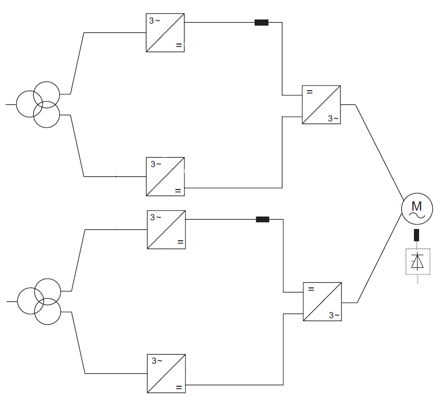
In this configuration, due to the 24-pulse rectifier section, it is necessary to use two 3-winding transformers or one 5-winding transformer. This increases the implementation cost of this design. As a result, this configuration is used in special cases.
In general, using configurations with more than 6 pulses increases the manufacturing cost. In these configurations, the control and driver system must be able to drive multiple power bridges simultaneously. This complicates the drive system. In addition, these configurations require the use of multi-winding transformers, which are more expensive than two-winding transformers. In 12 and 24 pulse configurations, it is also necessary to use two DC reactors or a special reactor configuration. As a result, using these configurations is complex and expensive.
In general, increasing the number of pulses in the rectifier section reduces current harmonics and increasing the number of pulses in the inverter section reduces torque ripple.
For example, in the 12-pulse model, the torque ripple is 3/1 of the 6-pulse model. Also, in the 12-pulse model, the 5th and 7th current harmonics are greatly reduced. The following is a comparison of current harmonics in 6-pulse and 12-pulse systems.
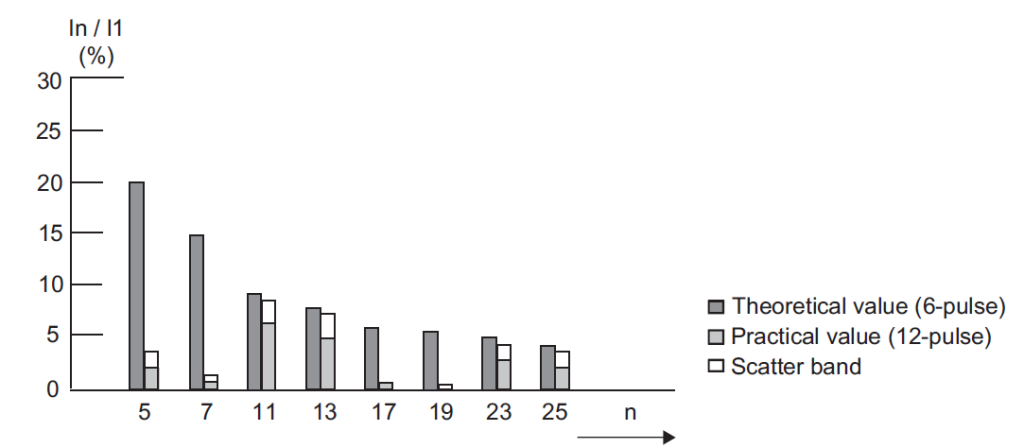
According to the above figure, if a 12-pulse configuration is used, the amplitude of current harmonics, especially the 5th and 7th order harmonics, is greatly reduced.
In 12-pulse and 24-pulse configurations that require more than one reactor, the reactor can be distributed differently in the distribution system. In this method, half of the reactor is placed in the positive path of the link and half in the negative path of the link, and the distributed reactor is distributed between two 6-pulse systems. The diagram of this configuration is shown below.
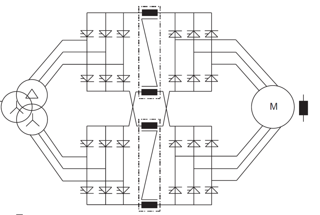
The use of the stated configuration for the reactor has the following advantages:
• The cost of manufacturing the reactor is reduced.
• The magnetic flux in the reactor core is reduced.
• The core losses of the reactor are reduced.
• The size of the reactor is reduced.
The distributed reactor configuration is a more efficient and cost-effective way to design a 12-pulse system. It is especially well-suited for applications where size and weight are important considerations.