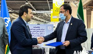
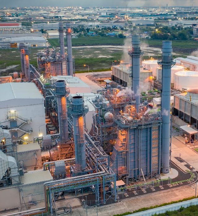
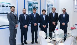
Signing of contract between Ahar Company and Abadan Oil Refining Company
On the sidelines of the second day of the 26th Oil, Gas, Refining and Petrochemical Exhibition, a memorandum of understanding was signed between Ahar and
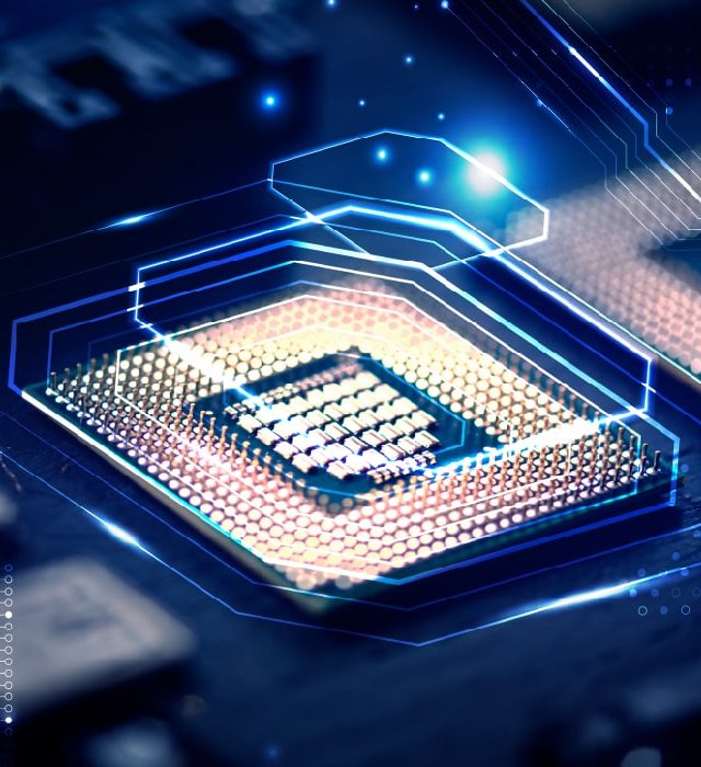
Ahar company started its activity in the field of electrical engineering services in electronics and control trends in 2000. These activities began with the redesign and production of power plant electronic boards and gradually extended to the design of advanced control systems needed in energy industries. In 2011, the turbine control system was presented which called Ramyar, and after that, the generator excitation system (Sanyar) and another advanced power plant, refinery, and oil and gas control systems were designed and presented
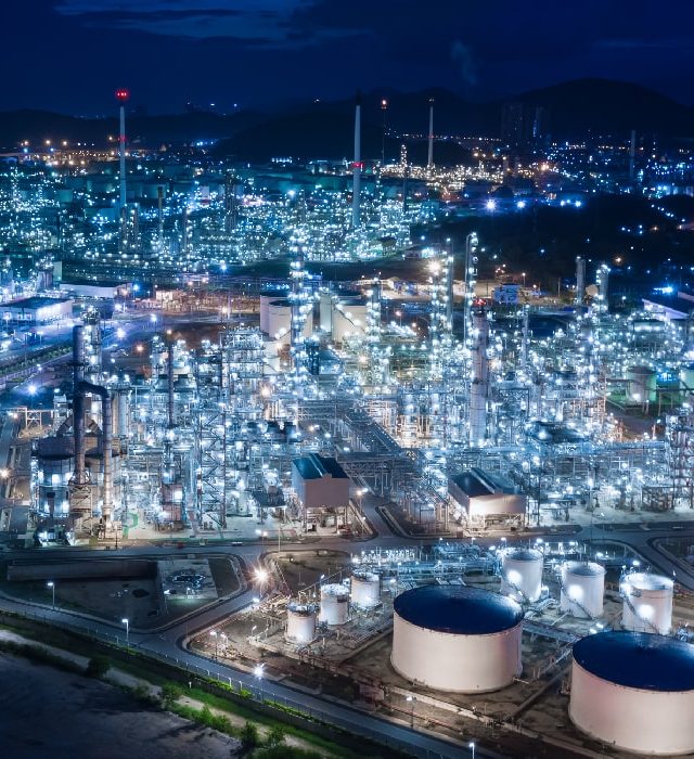
Today, a large number of power plants, refineries, oil transmission lines, etc. use Ahar control systems
Currently, the most important fields of activity of Ahar company can be summarized in the following fields
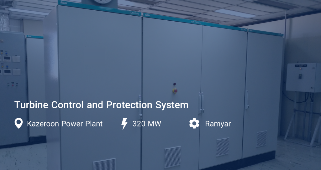
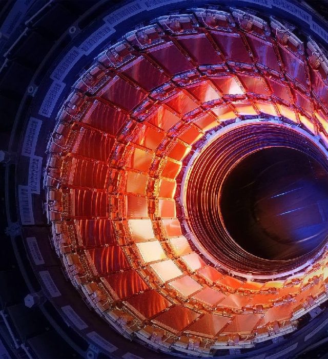
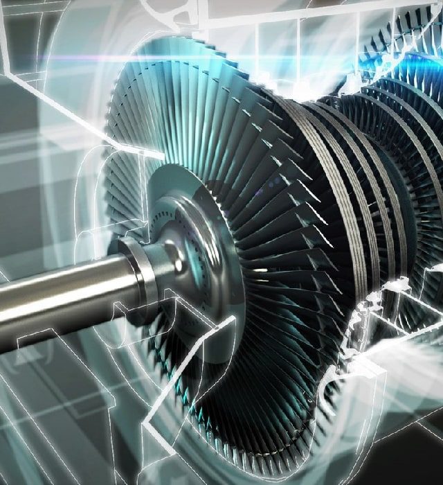
Ramyar’s product is a specialized controller for implementation on different types of turbines, including turbogenerators, turbopumps, and turbocompressors. This product covers all the processes of a gas or steam turbine, such as control, protection, supervision of all processes, monitoring, and application of operator commands
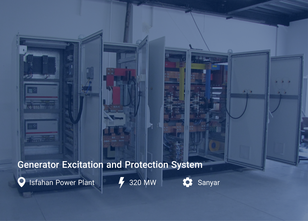
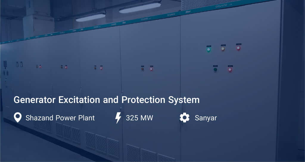
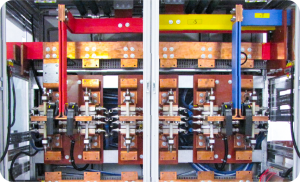
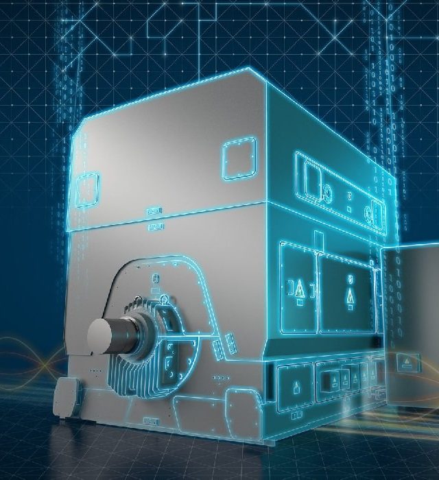
Sanyar’s product is a generator excitation and protection system based on the most up-to-date technology in the world, which is designed to control and protect synchronous generators. This system can include a wide range of generators in terms of size and type by using modular design, the possibility of redundant configuration and also choosing a wide range of thyristor/IGBT modules.
Redundancy in Engineering is one of the most important considerations for critical and sensitive applications such as power systems, avionics, and medical equipment.
A digital Generator Excitation Control System is an advanced system that uses digital control techniques to regulate the excitation of a generator.
Synchronous motors play a major role in today’s industry by providing higher productivity and also the possibility of designing and manufacturing in very large sizes. The biggest challenge of using synchronous motors is the need for a driver and its specific design for each motor. The driver of synchronous motors has very high technology and knowledge. The complexity and depth of this knowledge will double when we are dealing with large-size engines.
The Rayan P-10 series is designed to protect against overspeeding in high-sensitivity rotating machines
Its applications include speed protection in steam, gas, water turbines, and turbo compressors. This system is able to stop the unit through trip valves in case of Overspeed or over-acceleration
This system constantly monitors the speed of the rotor by monitoring the speed of pick-ups and stops the turbine when necessary with high security
Ramona is a native Iranian DCS that is fully compatible with the Yokogawa DCS system and is considered a suitable alternative for use in power plants, refineries, and all high-tech industries. In these products, the possibility of communication with the upstream departments, FCS, and HIS of Yokogawa is included, and all the settings that can be provided can also be defined in Ramona modules.
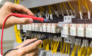
The pre-Compliance test is a test that is used before the main tests and only for the purpose of initial measurement of the manufactured products. It is cheap to use these tests and product defects are identified during the design process
including tests
IEC61000-4-3 (RF Interference)
IEC61000-4-4 (Burst)
IEC61000-4-8 (50Hz Magnetic Field)
Ramyar’s product is a specialized controller for implementation on different types of turbines, including turbogenerators, turbopumps, and turbocompressors. This product covers all the processes of a gas or steam turbine, such as control, protection, supervision of all processes, monitoring, and application of operator commands
Sanyar’s product is a generator excitation and protection system based on the most up-to-date technology in the world, which is designed to control and protect synchronous generators. This system can include a wide range of generators in terms of size and type by using modular design, the possibility of redundant configuration and also choosing a wide range of thyristor/IGBT modules.
Redundancy in Engineering is one of the most important considerations for critical and sensitive applications such as power systems, avionics, and medical equipment.
A digital Generator Excitation Control System is an advanced system that uses digital control techniques to regulate the excitation of a generator.
Synchronous motors play a major role in today’s industry by providing higher productivity and also the possibility of designing and manufacturing in very large sizes. The biggest challenge of using synchronous motors is the need for a driver and its specific design for each motor. The driver of synchronous motors has very high technology and knowledge. The complexity and depth of this knowledge will double when we are dealing with large-size engines.
The Rayan P-10 series is designed to protect against overspeeding in high-sensitivity rotating machines
Its applications include speed protection in steam, gas, water turbines, and turbo compressors. This system is able to stop the unit through trip valves in case of Overspeed or over-acceleration
This system constantly monitors the speed of the rotor by monitoring the speed of pick-ups and stops the turbine when necessary with high security
Ramona is a native Iranian DCS that is fully compatible with the Yokogawa DCS system and is considered a suitable alternative for use in power plants, refineries, and all high-tech industries. In these products, the possibility of communication with the upstream departments, FCS, and HIS of Yokogawa is included, and all the settings that can be provided can also be defined in Ramona modules.
The pre-Compliance test is a test that is used before the main tests and only for the purpose of initial measurement of the manufactured products. It is cheap to use these tests and product defects are identified during the design process
including tests
IEC61000-4-3 (RF Interference)
IEC61000-4-4 (Burst)
IEC61000-4-8 (50Hz Magnetic Field)
The latest completed projects of the Ahar company
On the sidelines of the second day of the 26th Oil, Gas, Refining and Petrochemical Exhibition, a memorandum of understanding was signed between Ahar and
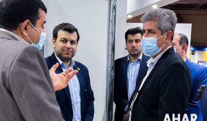
According to Mehr News Agency and Ahar Company, the 26th International Oil, Gas, Refining and Petrochemical Exhibition started on the morning of Friday 23 May
Tehran Oil Exhibition, which was not held on the usual date of each year (May) due to the outbreak of coronary heart disease this year,